eecs270.org
Project 7: Sequential Calculator
| Component | Points |
|---|---|
| Autograder Checkpoint | 10 |
| Autograder Final | 90 |
| Total | 100 |
Checkpoint: April 10, 2026 at 11:59 PM (ADD/SUB only) Final Due Date: April 20, 2026 at 11:59 PM
Note: There is no in-person signoff for this project. Grading is based on Autograder only.
Before Starting
- Review the lectures on RTL Design and Sequential Multiplication.
- Review the included starter and helper Verilog modules.
- Read the P7 FAQ to avoid common errors.
Starter Files
Provided helper modules (do not submit or modify these; they are built into the Autograder):
- Clock_Div.v : divides the 50 MHz clock by powers of 2 (use if timing fails).
- Binary_to_7SEG.v : renders signed-magnitude and two’s complement on HEX displays.
- SM2TC.v : signed-magnitude to two’s complement converter.
- TC2SM.v : two’s complement to signed-magnitude converter.
- FullAdder.v : single-bit full adder.
- AddSub.v : parameterized ripple add/subtract unit.
Reference Booth Multiplier implementation:
- BoothMul.v : parameterized sequential Booth multiplier (do not instantiate directly; embed the algorithm into your datapath).
Design Specification
The calculator performs addition (+), subtraction (-), multiplication (×), and division (/) on 11-bit two’s complement integers. Operands are entered as signed-magnitude and converted internally. This project is a basic example of Register Transfer Level (RTL) design: you will implement a datapath and controller.
I/O Interface
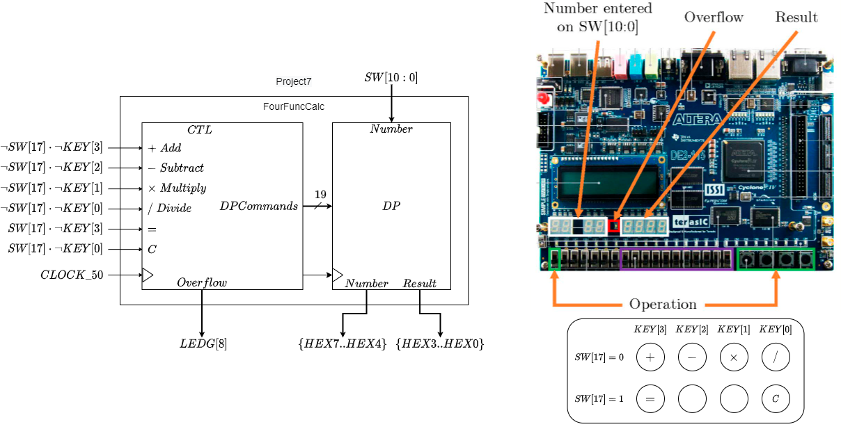
Figure 1: Four-Function Calculator Interface and Datapath/Control Decomposition
- Number entry: Signed-magnitude numbers in the range [-1023, 1023] are entered on
SW[10:0]and displayed on{HEX7, HEX6, HEX5, HEX4}. - Result display: Operation results are displayed on
{HEX3, HEX2, HEX1, HEX0}. Values outside [-999, 999] are shown as----(“can’t be displayed”). - Operations: With
SW[17] = 0, a KEY press selects an arithmetic operation (+, -, ×, /) per the mapping in Figure 1. - Commands: With
SW[17] = 1:KEY[3]==(equals): display the result of the current operation on{HEX3..HEX0}.KEY[0]= C (clear): clear the result and return to the initial state.
- Overflow:
LEDG[8]is asserted if a result falls outside the 11-bit two’s complement range [-1024, 1023], or on divide-by-zero. - Clock: Uses the built-in 50 MHz
CLOCK_50.- If your design simulates correctly but fails on hardware, use
Clock_Div.vto divide the clock by a power of 2 to eliminate timing violations.
- If your design simulates correctly but fails on hardware, use
Modules
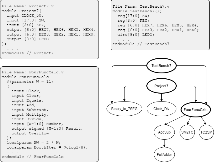
Figure 2: Module Instantiation Graph. You only need to implement the three bolded modules.
You implement three modules (bolded in Figure 2): Project7, TestBench7, and FourFuncCalc (plus any lower-level modules you introduce). The remaining six modules are provided. The FourFuncCalc.v starter template declares a framework for the datapath components; your job is to complete the datapath and create the controller (state encoding, transitions, and command signals).
Operation
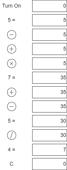
Figure 3: Typical Usage Scenario
- On power-on, the calculator displays 0.
5 =displays 5.- Pressing any sequence of operation keys has no effect until another number is entered; the performed operation is the last one selected.
7 =after×displays 35 (5 × 7).- 5 =displays 30 (35 - 5)./ 4 =displays 7 (30 / 4).Cdisplays 0.
Datapath
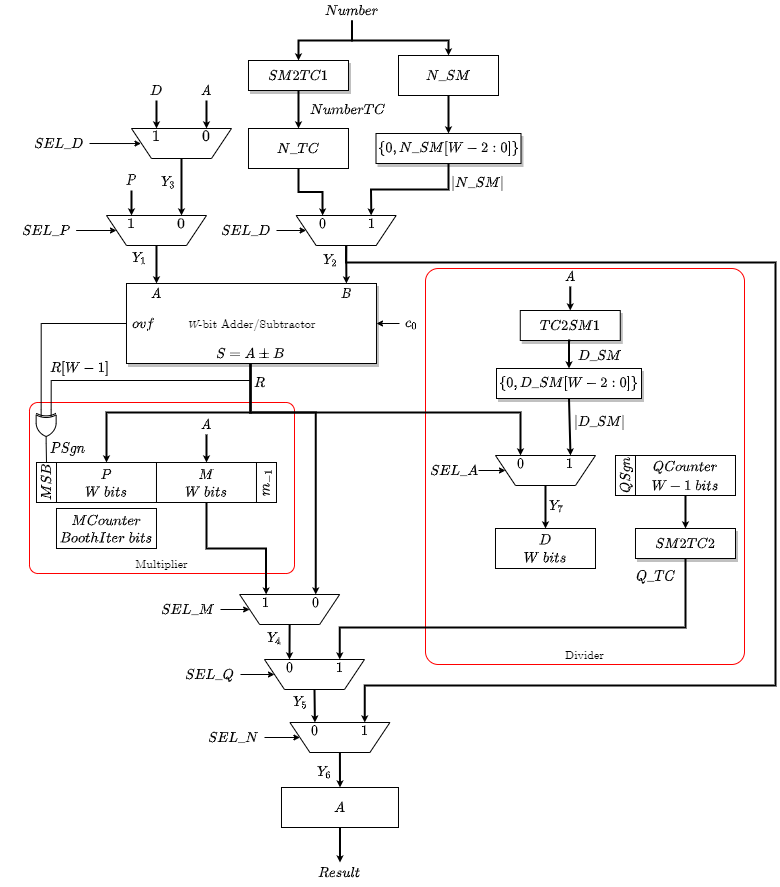
Figure 4: Four-Function Calculator Datapath
Your controller must target the datapath in Figure 4, which uses a single 11-bit adder/subtractor shared across all four operations via multiplexing. A controller designed for a different datapath (e.g., using more than one add/subtract unit) will lose points.
Abstract State Transition Graph
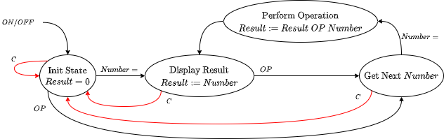
Figure 5: High-Level Abstract State Transition Graph
- Start from the abstract state diagram in Figure 5 and incrementally refine it as you add operations.
- Implement and verify LOAD first, then ADD, then SUB, then MUL, then DIV. Each operation adds states to the refined STG.
- Overflow detection requires a terminal overflow state reachable from each arithmetic path. The calculator remains in the overflow state until cleared by
C.
Division Primer
Division is not covered in lecture. We begin by defining a few terms: Quotient = Dividend / Divisor. The Dividend is the number being divided, the Divisor is the number we are dividing by, and the Quotient is the result of the division. In this project, we round towards zero, so 7 / 2 = 3 and -7 / 2 = -3.
The algorithm used in the datapath is relatively simple: repeatedly subtract the divisor’s magnitude from the dividend’s magnitude, and keep count of how many times you need to subtract before the dividend becomes negative. This algorithm requires positive operands, so the datapath extracts magnitude and sign from an inputted signed-magnitude number and converts the result into two’s complement.
Division with only the magnitude of the operands discards information about the sign. The quotient’s sign is determined by XORing the signs of the dividend and divisor: sign(Quotient) = sign(Dividend) XOR sign(Divisor). If dividend and divisor are both negative or both positive, the sign is positive (0). If one is negative and the other is positive, the sign is negative (1).
If the divisor is zero, treat this as an overflow case.
Example: -7/2
In this case, -7 is the dividend and 2 is the divisor. We start by calculating the sign:
Sign(Quotient) = sign(-7) XOR sign(2) = 1 - The quotient will be negative.
We use the magnitudes to perform the division, so we compute 7/2:
| Step | Dividend | Quotient |
|---|---|---|
| Start | 7 | Quotient = 0 |
| 1 | 7-2=5 | Quotient = 1 |
| 2 | 5-2=3 | Quotient = 2 |
| 3 | 3-2=1 | Quotient = 3 |
| 4 | 1-2=-1 | Stop |
We stop once the dividend becomes negative. The exact quotient is 3.5, but we round towards zero to get 3. Finally, we apply the sign to get the final result of -3.
Design Notes and Hints
- The arithmetic core is the provided parameterized
AddSubmodule. Share it across all four operations as shown in the datapath. - Multiplication: embed the parameterized Booth Multiplier algorithm from the Sequential Multiplication lecture into the Figure 4 datapath (do not instantiate
BoothMuldirectly). Overflow is asserted if the product cannot be fully represented in only W bits. - Operands use signed-magnitude encoding externally; convert to/from two’s complement via the provided
SM2TC/TC2SMmodules. - Debug in ModelSim before testing on the DE2-115 board. Add state labels to your
.dofile so transitions are readable in the Waveform view. - Parameterize by width
W. Use a smallW(e.g., 4) in simulation to quickly find functional errors, then verify corner cases withW = 11. - If the design simulates correctly but fails on hardware, use
Clock_Div.vto divide the 50 MHz clock by a power of 2 to eliminate timing violations.- Most designs will work with the base 50 MHz clock. If you need to slow the clock, you might want to consider optimizing your design to meet timing without the clock divider.
Deliverables
| File Name | Task | Testing Process | Grading Process |
|---|---|---|---|
FourFuncCalc.v |
Implement the controller and datapath state updates for the four-function calculator | ModelSim | Autograder |
TestBench7.v |
Write test cases covering all four operations, overflow, and divide-by-zero | ModelSim | Autograder |
Project7.v |
Connect FourFuncCalc to the DE2-115 switches, keys, HEX displays, and LEDs |
LabsLand / Quartus | Autograder |
Do not submit the six provided helper modules (Clock_Div, Binary_to_7SEG, SM2TC, TC2SM, FullAdder, AddSub) as they are built into the Autograder. Submit only the files above plus any additional lower-level modules that you author.
No in-person signoff. The 4/10 checkpoint tests ADD/SUB via Autograder; the 4/20 final submission tests all four operations on Autograder and Quartus. Do not modify file names, module names, or interfaces of the starter files.