eecs270.org
Project 6: Traffic Light Controller
| Component | Points |
|---|---|
| Autograder | 75 |
| Lab Signoff | 60 |
| Total | 135 |
Due Date: April 1, 2026 at 11:59 PM
Before Starting
Helpful references:
Starter Files
Design Specification
Design a traffic light controller for an intersection involving a main east-west road and a side north-south road. Analyze the requirements in detail before writing any Verilog.
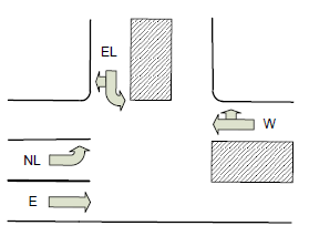
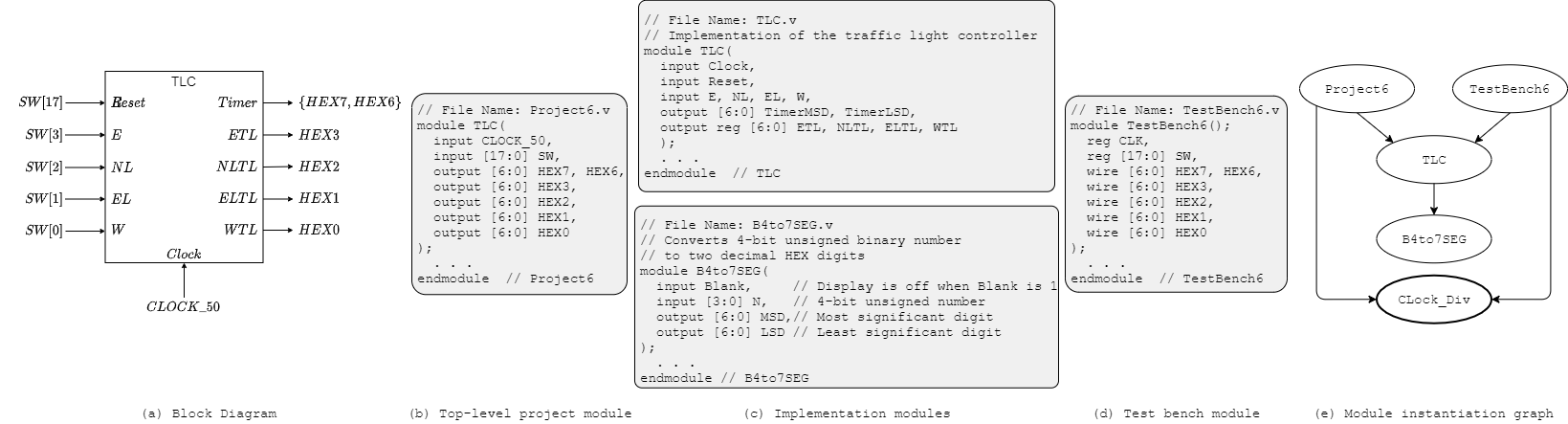
Figure 1: Traffic intersection, controller interface, module decomposition, and module instantiation graph
The intersection allows three traffic flows:
- Flow A: east and west on the main road
- Flow B: east on the main road and north-left from the main road to the side road
- Flow C: east-left from the side road to the main road
Inputs and Outputs
- Inputs
- Traffic sensors (1-bit each; ON = car present, OFF = no car)
E: East-bound straightNL: North-bound leftEL: East-bound left (and west right)W: West-bound straight (and north right)
ClockReset
- Traffic sensors (1-bit each; ON = car present, OFF = no car)
- Outputs
- Traffic lights (Green/Yellow/Red)
ETL: east-bound straightNLTL: north-bound leftELTL: east-bound leftWTL: west-bound straight
Timer
- Traffic lights (Green/Yellow/Red)
Controller states must be represented by positive edge triggered DFFs. The controller has a synchronous Reset input that, when HIGH, sets the next state to traffic flow A and resets the timer to 10.
The Timer output counts down and is displayed in decimal much like a pedestrian crosswalk timer.
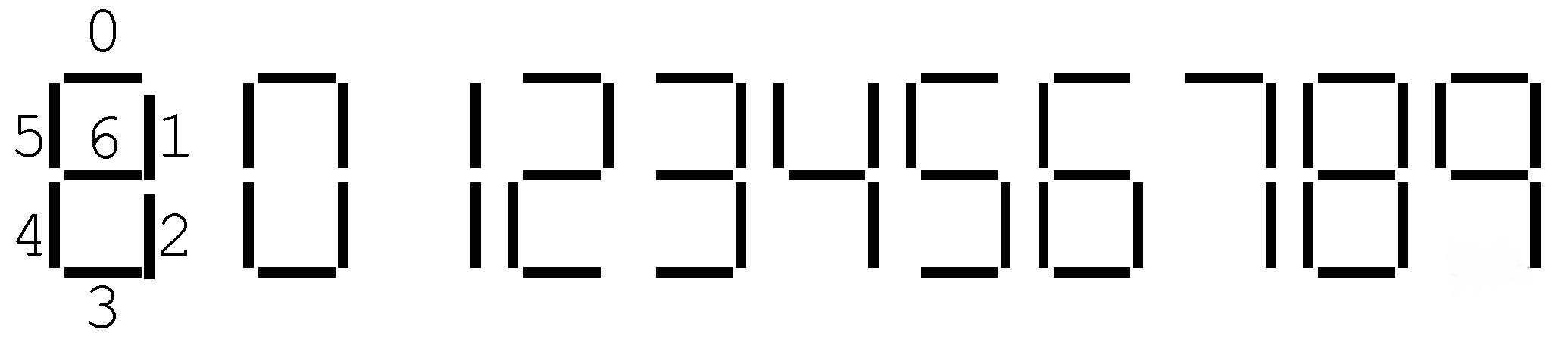
Figure 2: Displaying Numbers for the Timer
Operation Rules
- A Green light must remain Green for intervals that are multiples of 10.
- When no sensor is on, the three flows cycle in the order Flow C, Flow B, Flow A, Flow C, …
- Only one flow can be green at a time.
- Conflicts among all three flows are resolved by giving Flow A priority over Flow B, Flow B over Flow C, and Flow C over Flow A.
- When a light changes from Green to Red, it must be Yellow for exactly 1 cycle in between. A light may never go from Yellow to Green, nor from Red to Yellow. The Timer counts down from 10 to 1 when the light is Green and is blank when the light is Yellow.
- No starvation. If a sensor is on that isn’t covered by the current flow, its lane must get a Green light as soon as the current conflicting flow ends its 10 cycle Green interval and 1 cycle Yellow interval.
- When only one sensor is on, that light will become Green and stay Green until some other sensor input changes (without violating the other rules). In this case, there should be no Yellow states.
- No light combinations beyond Flow A, Flow B, and Flow C are allowed (excluding yellow transition states).
Mapping Light Colors to HEX Displays
The HEX displays indicate colors by their first letter in lowercase as shown below.

Figure 3: Displaying Green (g), Yellow (y), and Red (r)
Modules
TLC: Implements the controller functionality. Its inputs and outputs are the internal signal names shown in Figure 1.B4_to_7SEG: Helper module that converts an unsigned 4-bit binary number to two decimal digits rendered on a pair of 7-segment HEX displays.Clock_Div: Provided to you (do not write it). Generates an slower clocks from the 50 MHzCLOCK_50input.
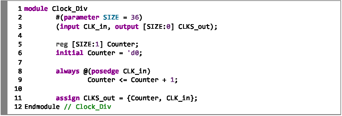
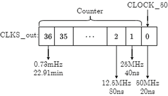
Figure 4: The Clock_Div module
Instantiate Clock_Div with CLOCK_50 and tap the output array at the appropriate index to derive a 2 Hz clock ():
wire [36:0] CLOCKS;
wire clk;
Clock_Div (CLOCK_50, CLOCKS);
assign clk = CLOCKS[i];  // pick i for ~2 Hz
The frequency at index i of CLOCKS is:
f[i] = (50 × 106) / 2i Hz
Pick the index that yields the closest approximation to a 0.5-second period without exceeding it.
Design Notes and Hints
- This is a fairly complex design project. DO NOT START WRITING VERILOG CODE BEFORE YOU SPEND SOME TIME ANALYZING THE REQUIREMENTS AND GAINING A GOOD UNDERSTANDING OF HOW TO STRUCTURE YOUR CODE.
- Implement the Timer as a counter. Think about how to initialize it, when to start it, when to stop it, and what happens when it expires.
- Use Verilog
parameters to name states and HEX bit patterns. - You should need no more than four bits to track the controller state.
- Assign full 7-bit patterns to HEX displays (e.g.,
HEX1 = 7'b0010010;), not individual segments. Use parameters for readability.
Deliverables
| File Name | Task | Testing Process | Grading Process |
|---|---|---|---|
| TLC.v | Implement the traffic light controller | ModelSim | Autograder |
| B4_to_7SEG.v | Implement the 4-bit binary to 2-digit decimal HEX converter | ModelSim | Autograder |
| TestBench6.v | Write test cases for TLC | ModelSim | Autograder |
| Project6.v | Connect TLC and Clock_Div to FPGA pins | LabsLand | Signoff |
To ensure that your design works with the Autograder, do not modify file names, module names, or interfaces for any of the starter files. All files must be submitted to the Autograder for grading and feedback.
The signoff will be conducted in your assigned lab sections the week after the project deadline.