eecs270.org
Project 0: Majority (Tutorial)
This tutorial walks through entering, compiling, simulating, and testing a simple Verilog design. Unlike later projects, all source files are provided complete so you can practice the workflow.
Starter Files
- Project0.v
- TestBench0.v
- Majority.v
- wave0.do (ModelSim macro file)
Design Specification
Design a logic circuit that takes 3 binary inputs a, b, c and returns a binary output m that is 1 when two or more inputs are 1. This is the Majority function over 3 inputs.
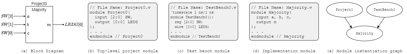
Figure 1: Project 0 interface and module instantiation graph. Majority is instantiated by both Project0 and TestBench0.
The design is split into three Verilog modules:
Majority: implements the function in terms of formal inputsa,b,cand formal outputm.Project0: top-level module that connectsMajorityto the DE2-115 board’s switches and LED.TestBench0: instantiatesMajorityfor ModelSim simulation. Inputs are declaredregand outputswire(covered later in the course).
This three-module structure (top-level Project*, TestBench*, and an implementation module) is the template every project in the course follows.
Module Instantiation Graph. A Verilog module is the basic hardware unit. Complex designs are decomposed into multiple modules, and the relationships are shown in a module instantiation graph. An arrow from module A to module B means A instantiates a copy of B.
Verilog Implementation
Project0 Module
// File Name: Project0.v
module Project0
(
    input  [2:0] SW,    // a, b, c
    output [0:0] LEDG   // m
);
    Majority M(.m(LEDG[0]), .b(SW[2]), .a(SW[1]), .c(SW[0]));
endmodule
Figure 2: Top-level Project0 module
- Comments:
//for single-line,/* ... */for block comments. - Lines 3–6 declare the I/O.
SWis a 3-bit input array (SW[2:0]);LEDGis a 1-bit output. Verilog requires both indices in a range declaration even when they are equal -output [0] LEDGis invalid. - Line 8 instantiates
Majorityas instanceMand connects formals to actuals by name (.formal(actual)). The order of arguments doesn’t matter with this syntax. Equivalent positional syntax:Majority M(SW[2], SW[1], SW[0], LEDG[0]);.
Majority Module
The output is m = a&b | a&c | b&c. Two implementation styles produce the same circuit:
Behavioral:
// File Name: Majority.v
module Majority (
    input  a, b, c,
    output m
);
    assign m = a && b || a && c || b && c;
endmodule
The assign keyword indicates m is a combinational signal - it’s re-evaluated whenever any right-hand-side input changes (continuous assignment). This is Behavioral Modeling: specify the function with Boolean expressions.
Structural (a netlist of gates):
// File Name: Majority.v
module Majority (
    input  a, b, c,
    output m
);
    wire ab, ac, bc;
    and a1(ab, a, b);
    and a2(ac, a, c);
    and a3(bc, b, c);
    or  o1(m, ab, ac, bc);
endmodule
Gate instantiations follow the template <gate-type> instance-name (output, input_1, ..., input_n). Gate types must be lowercase - AND, And, etc. are not recognized.
TestBench0 Module
// File Name: TestBench0.v
`timescale 1 ns/1 ns
module TestBench0();
    reg  [2:0] SW;
    wire [0:0] LEDG;

    Majority M(.a(SW[2]), .b(SW[1]), .c(SW[0]), .m(LEDG[0]));

    initial begin
        SW = 3'b000; #5;
        SW = 3'b001; #5;
        SW = 3'b010; #5;
        SW = 3'b011; #5;
        SW = 3'b100; #5;
        SW = 3'b101; #5;
        SW = 3'b110; #5;
        SW = 3'b111; #5;
    end
endmodule
Figure 3: Test bench for Majority
- Line 2 sets the simulation time scale: 1 unit = 1 ns, with 1 ns resolution.
- Argument list is empty - testbenches are purely simulations and don’t take I/O.
- Inputs to the device under test are declared
reg; outputs arewire. - The
initial begin ... endblock enumerates all 8 input combinations, applying each for 5 time units. ModelSim executes these sequentially.
Simulation and Testing
ModelSim
Simulate your design in ModelSim before submitting. See the ModelSim Quick Start for step-by-step setup with this project.
Local Simulation (alternative)
You can also simulate locally with iverilog and gtkwave/VaporView. See the Local Simulation Tools Setup Guide.
Autograder
Submit your code to the EECS 270 Autograder. The Autograder builds a testbench around your top-level module and a reference module, runs comparison tests, and reports one of:
- Syntax errors: fix in ModelSim before resubmitting.
- Failed tests: the Autograder shows the failing input pattern, the expected output, and your output. Reproduce in ModelSim, fix, and resubmit.
- All tests pass: verify the top-module on LabsLand. Resubmit to Autograder if you find issues.
LabsLand Verification
After simulation passes, verify on a real DE2-115 board through LabsLand. See the LabsLand Verification Guide.