eecs270.org
Project 1: Selector
| Component | Points |
|---|---|
| Autograder | 50 |
| Lab Signoff | 25 |
| Total | 75 |
Due Date: January 20, 2026 at 11:59 PM
Before Starting
To ensure you have the necessary tools to complete this project, please make sure you have completed the tutorial project.
Additional helpful resources:
Starter Files
Design Specification
The goal of this project is to design a Selector circuit that chooses between two sets of 7-bit inputs. In this project, you will need to use structural Verilog to design the modules.
Logic Modules: Selector and SEL1
The Selector module contains the 7-bit selection logic.
Selector interface:
| Net | Size | Direction | Description |
|---|---|---|---|
A |
7 bits | Input | First 7-bit input |
B |
7 bits | Input | Second 7-bit input |
sel |
1 bit | Input | Select signal |
F |
7 bits | Output | Output of the selector |
When sel is 0, the output F should equal input A; when sel is 1, the output F should equal input B.
The SEL1 module is a 1-bit 2-to-1 selector circuit.
SEL1 interface:
| Net | Size | Direction | Description |
|---|---|---|---|
a |
1 bit | Input | First 1-bit input |
b |
1 bit | Input | Second 1-bit input |
sel |
1 bit | Input | Select signal |
f |
1 bit | Output | Output of the selector |
When sel is 0, the output f should equal input a; when sel is 1, the output f should equal input b.
Implement Selector by instantiating 7 copies of SEL1 using implicit instantiation. You must use structural Verilog to write the logic for both the Selector and SEL1 modules. Refer to Project 0 for structural Verilog examples.
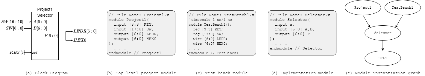
Top-level: Project1 Module
This module’s interface is given in Project1.v. This module interfaces the Selector module with the FPGA pins.
Top-level Project1 interface:
| Net | Direction | Physical Description | Correspondence to Selector |
|---|---|---|---|
SW[6:0] |
input | rightmost switches | input B |
SW[16:10] |
input | leftmost switches | input A |
KEY[3] |
input | leftmost button | select signal |
LEDR[6:0] |
output | red LEDs | output F |
HEX0[6:0] |
output | 7-segment display | output F |
The Selector output F should be simultaneously displayed on both LEDR[6:0] and HEX0. When KEY[3] is pressed, F should select A. When KEY[3] is not pressed, F should select B.
Testbench1 Module
You will need to write a testbench to verify the functionality of your Selector module. A starter framework is provided in TestBench1.v. You will need to add test cases to adequately test your design. Your testbench will also be submitted to the Autograder to ensure that your tests have good coverage of the design specification.
In total, the selector module has 15 inputs (7 bits for A, 7 bits for B, and 1 bit for sel), so there are 2^15 = 32768 possible input combinations. It is not feasible to test all possible combinations, so you will need to think carefully about how to select a smaller set of test cases that still provides good coverage of the design specification.
Design Notes and Hints
- The seven segments in the HEX displays are numbered 0 to 6 as shown below. Segment i in HEX0 would be accessed as HEX0[i].
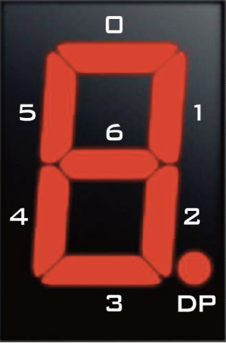
- The HEX outputs are active low. To turn on a segment, you need to drive it to 0; to turn it off, drive it to 1.
- The KEY inputs are also active low. When a KEY is pressed, it outputs 0; when it is not pressed, it outputs 1.
Deliverables
| File Name | Task | Testing Process | Grading Process |
|---|---|---|---|
| Selector.v | Implement 7-bit Selector module | ModelSim | Autograder |
| SEL1.v | Implement 1-bit SEL1 module | ModelSim | Autograder |
| TestBench1.v | Write test cases for Selector module | ModelSim | Autograder |
| Project1.v | Connect Selector module to FPGA inputs | LabsLand | Signoff |
To ensure that your design works with the Autograder, do not modify file names, module names, or interfaces for any of the starter files. All files must be submitted to the Autograder for grading and feedback.
The signoff will be conducted in your assigned lab sections the week after the project deadline.